
Summary
This article will guide you through the architecture and development tools of the PSOC™ Control C3 MCU and demonstrate how to create a project using Eclipse IDE for ModusToolbox™. Through this implementation example utilizing the smart I/O peripheral, you will learn how to connect a button input pin to an output pin via smart I/O to drive an external LED. Once initialized, it operates automatically without CPU involvement, allowing you to further experience the low-power and high-integration features of the PSOC™ Control C3.
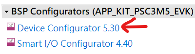
Software Download and Installation
Software version
ModusToolbox™ software3.4 or above.
To access the growing number of PSOC™ Control C3 code examples using ModusToolbox™, please visitGitHubWebsite.
The EVK used in this article is KIT_PSC3M5_EVK. For more details, please refer to.KIT_PSC3M5_EVK 。
The article begins
1. Create an Empty App project. (You can refer to the previous article for the steps. Click here )
2. This design uses Smart I/O to connect the button input pin to the Smart I/O output pin, enabling the toggling of an external LED through the LUT functionality of the Smart I/O resource.

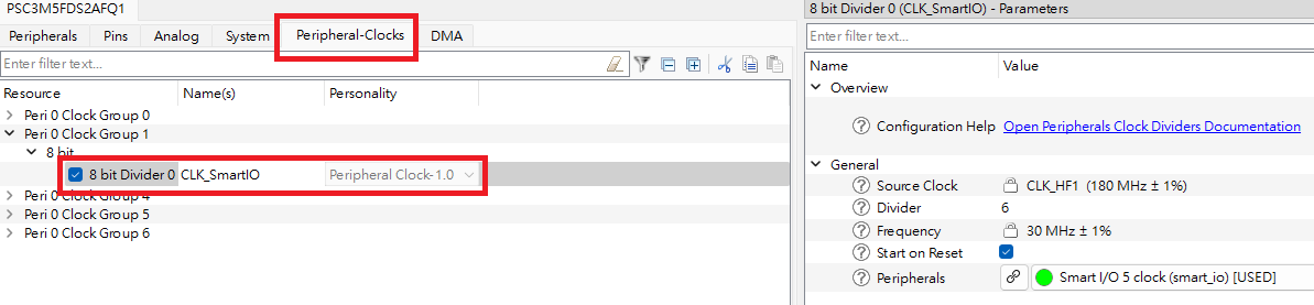
3. In Device Configuration, configure I/O.
4. In Device Configuration, configure the Smart IO Clock.
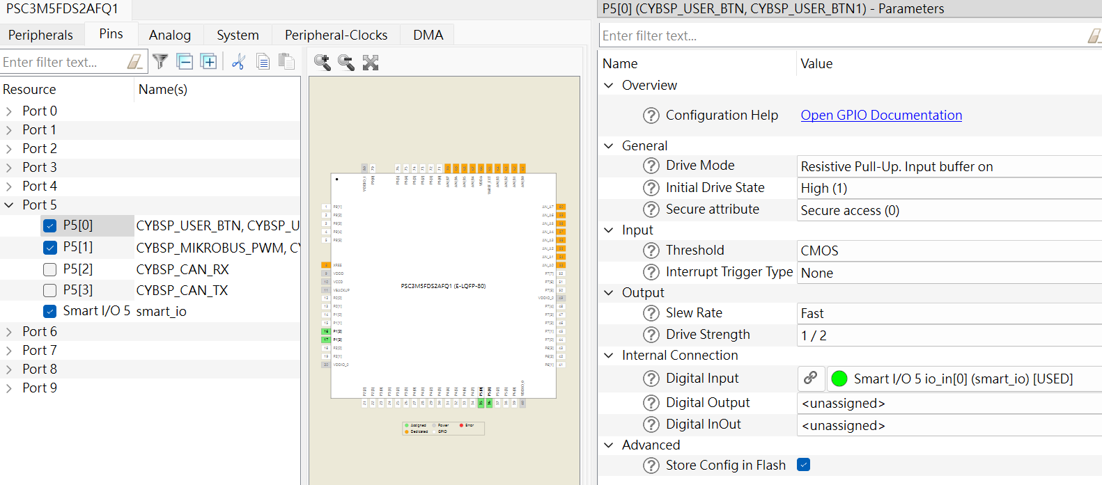
5. Select Input / Output in Pins.
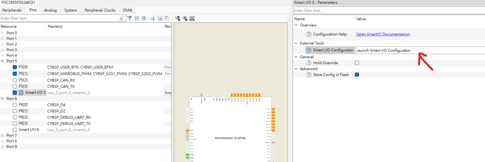
5.1 Select P5[0] as Smart I/O 5 input
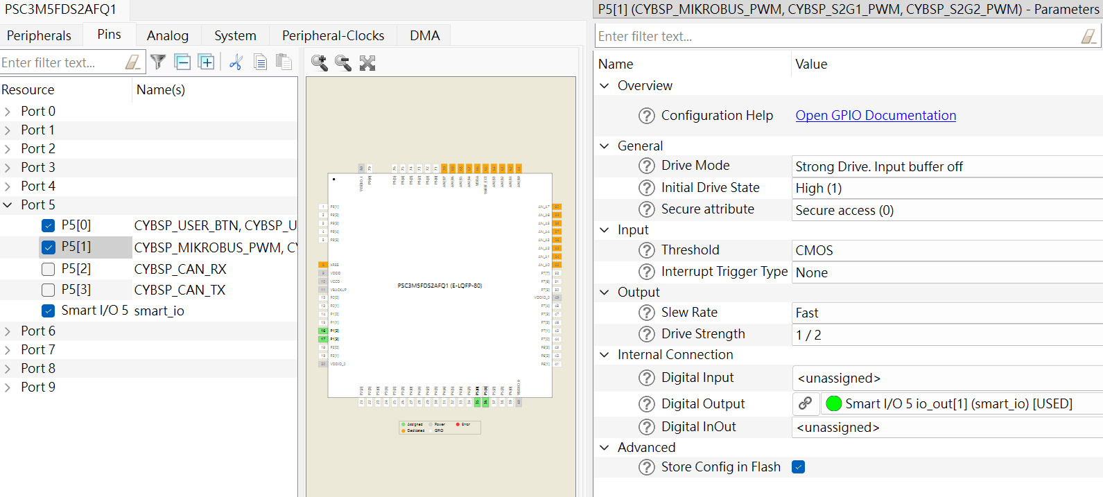
5.2 Select P5[1] as Smart I/O 5 output
5.3 Check Smart I/O 5 and click on 'Smart I/O Configurator'.
5.4 Configure I/O in the Smart I/O Configurator
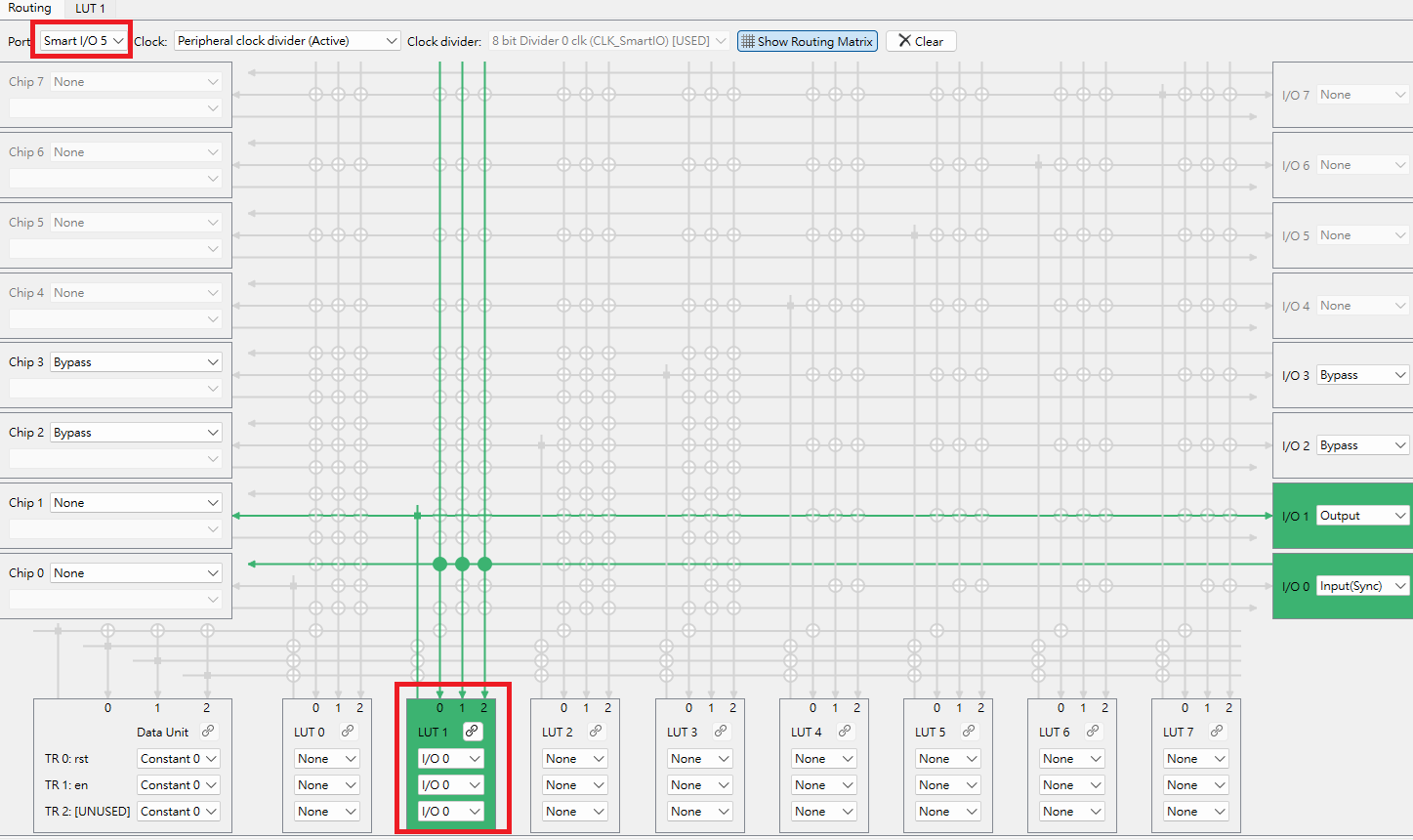
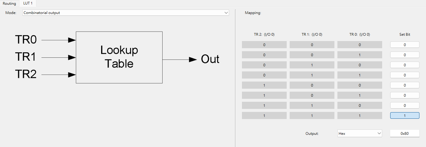
5.5 Configure LUT in Smart I/O Configurator
6. Part of the program
Initialize the Smart I/O module. The Smart I/O connects the button input pin to the output pin to toggle the external LED indicator.
Cy_SmartIO_Init(smart_io_HW, &smart_io_config);
Enable Smart I/O
Cy_SmartIO_Enable(smart_io_HW);
The LED flashing effect is generated by smart I/O hardware through button presses, without using the CPU.
Conclusion
Smart I/O brings a higher level of I/O control flexibility and low-power advantages to the PSOC™ Control C3 microcontroller. With built-in programmable logic (such as AND, OR, XOR) and a three-input lookup table (LUT), Smart I/O enables complex logic operations and input/output control without occupying CPU resources, further simplifying hardware design and reducing power consumption. Its structure, located between the HSIOM and I/O ports, allows signals to undergo pre-processing and post-processing before entering or leaving the MCU, providing high integration and the shortest signal response path. Additionally, Smart I/O supports most power modes (except Hibernate) and features clock selection and synchronization capabilities, making it particularly outstanding in high-reliability and low-power application scenarios.
Through this example, we demonstrate how to use only Smart I/O hardware logic to achieve button-controlled LED blinking without the need for CPU intervention. This not only highlights the flexibility and performance of PSOC™ Control C3 in smart peripheral applications but also lays a solid foundation for more complex logic control and energy-efficient designs in the future.