
Summary
The next generation of HVAC and heat pump systems needs to meet the challenges of high performance, strong safety, and fast time-to-market. Infineon has introducedPSOC controls the C3 microcontrollerThe microcontroller integrates a 180MHz Arm® Cortex®-M33 core, a CORDIC accelerator, high-speed 12Msps ADC, multi-channel comparators, and high-precision TCPWM modules, optimized for dual motor and power control applications. It features platform-level security functions (including TrustZone® and a hardware encryption unit) and supports OTA firmware updates to meet the security needs of modern devices. Combined with ModusToolbox™ and HVAC-specific reference designs, the PSOC Control C3 accelerates the design process, providing OEMs with flexible, reliable, and high-performance control solutions.
This article will help you explore the architecture and development tools of the PSOC™ Control C3 MCU, and demonstrate how to create your first project software using the Eclipse IDE for ModusToolbox™. It will also showcase a GPIO example. By working with GPIO, you will learn how to use ModusToolbox™ to control the PSOC™ Control C3 MCU.
Software Download and Installation
Software version
ModusToolbox™ software3.4 or above.
To access the growing number of PSOC™ Control C3 code examples using ModusToolbox™, please visitGitHubWebsite.
The EVK used in this article is KIT_PSC3M5_EVK. For more details, please refer to the documentation.KIT_PSC3M5_EVK 。
The article begins
1. Click 'File' → 'New' → 'ModusToolBox™ Application'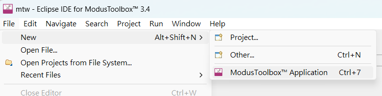
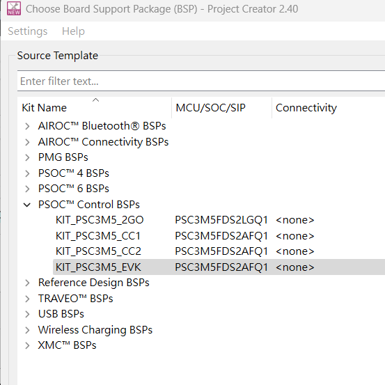
2. Select KIT_PSC3M5_EVK
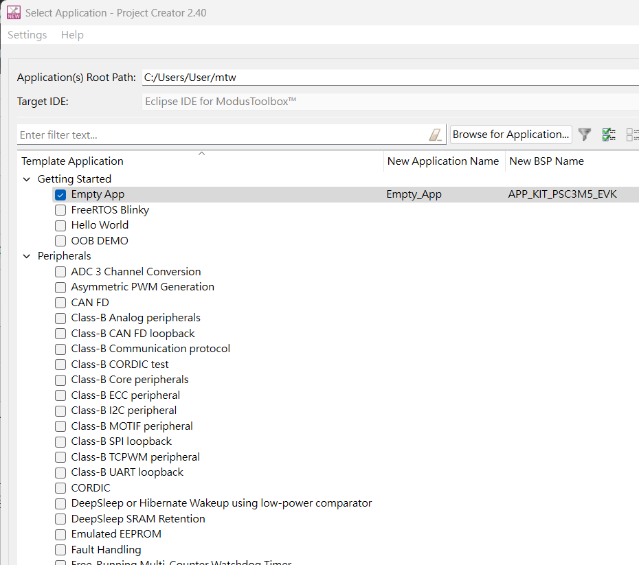
3. There are many examples, and the following creates an Empty App as an example.
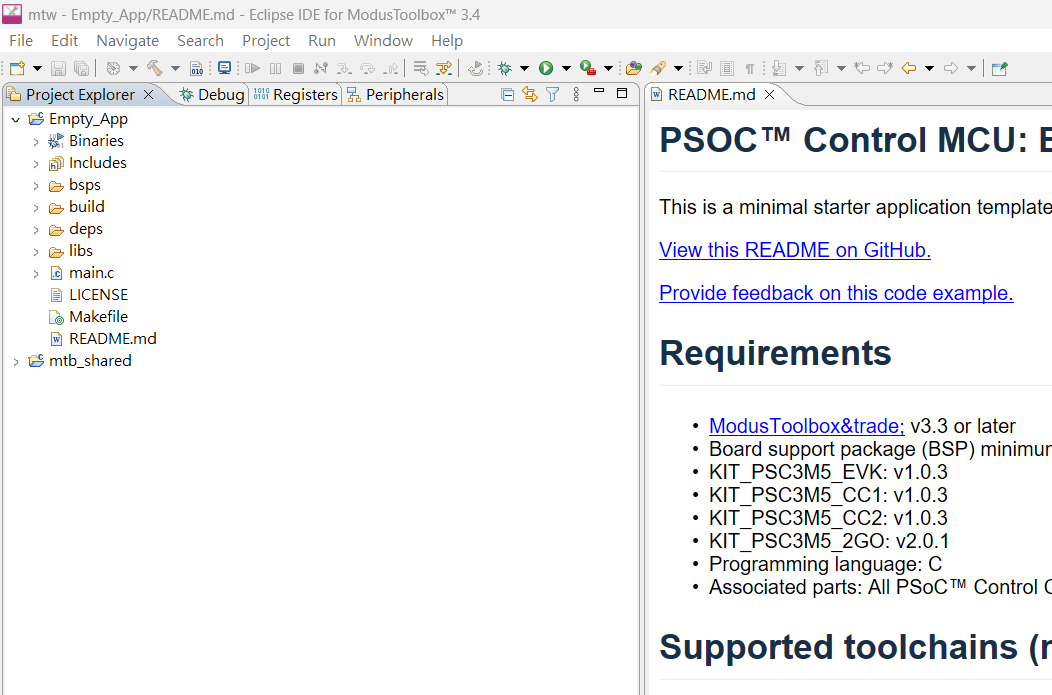
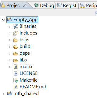
4. After the addition is complete, you can see the created Empty_App project in the Solution Explorer. At the same time, the Readme.md file will be displayed in the right-hand window, providing an introduction to how to use this example.
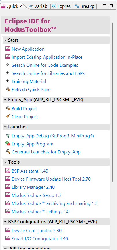
5. Click Empty_App
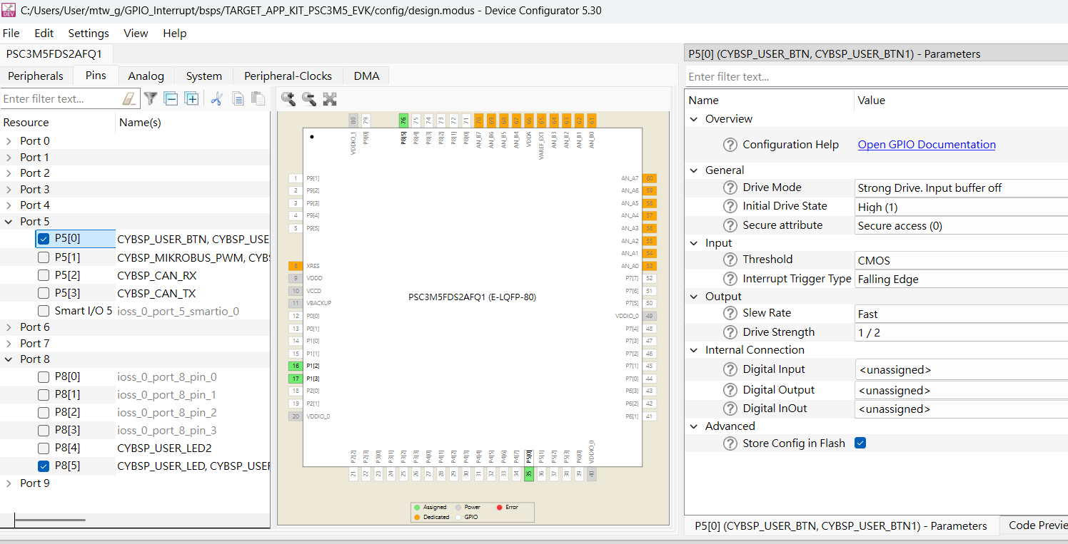
6. In the quick panel below, you will see many options. Click on the bottom option, Device Configurator 5.30.
7. Navigate to the peripheral configuration page of PSOC™ Control C3, as shown below, and select Port2→P2[0]. In the parameter section on the right, you can configure many options for this GPIO. For detailed information, click on Configuration Help and select Open GPIO Documentation.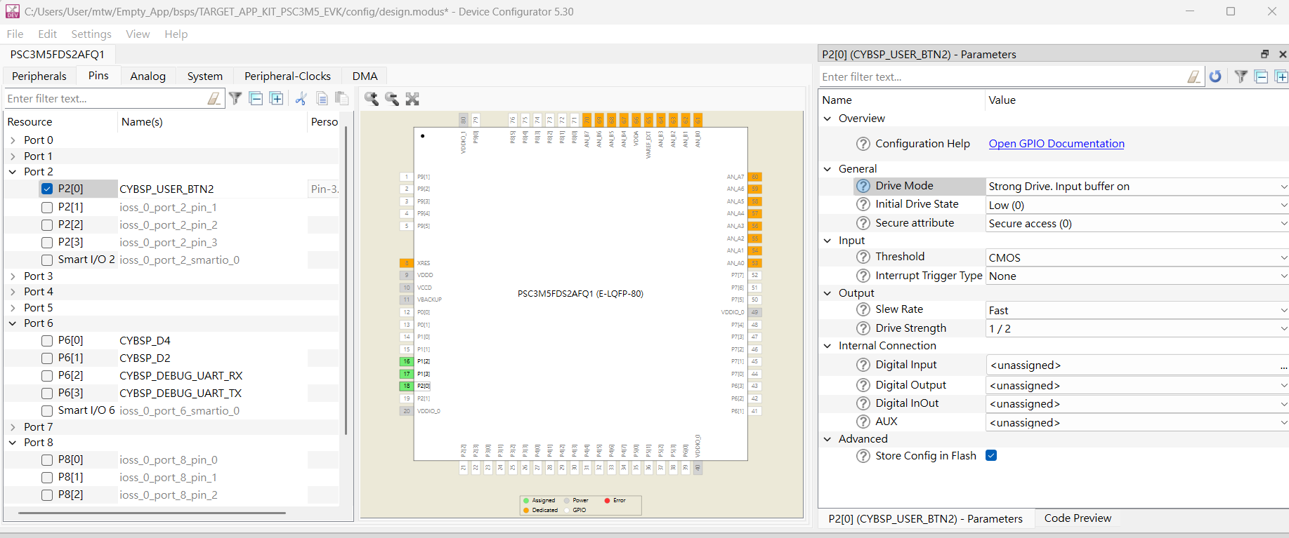
8. In terms of GPIO drive modes, PSOC™ Control C3 offers a wide range of configurations.
There are eight main drive modes here. The following illustrations are for CPU registers, UDB/DSI digital peripherals, and fixed-function peripherals.
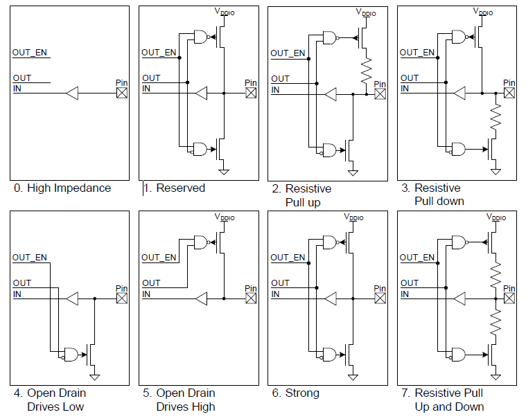
In each mode, a simplified diagram of the output driver structure as seen from the pin perspective.
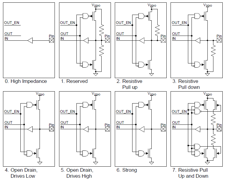
High-ImpedanceThis is the standard high-impedance (HI-Z) state, recommended for both analog and digital inputs. For digital signals, the input buffer is enabled; whereas for analog signals, the input buffer is typically disabled to reduce crowbar current and leakage in low-power designs. To achieve the lowest chip current, unused GPIOs must be set to high-impedance mode with the input buffer disabled. The high-impedance mode with the input buffer disabled is also the default reset state of the pin.
Resistive Pull-Up or Resistive Pull-Down:The resistive mode provides a series resistor in one data state and strong drive in the other state. Pins in these modes can be used as digital inputs or digital outputs. If a resistive pull-up is needed, the data register bit for the pin must be written to '1'. If a resistive pull-down is needed, the data register bit for the pin must be written to '0'. Connecting mechanical switches is a common application for these drive modes. The resistive mode is also used for connecting PSoC and open-drain drive lines. A resistive pull-up is used when the input is open-drain low, while a resistive pull-down is used when the input is open-drain high.
Open Drain Drives High and Open Drain Drives Low:The open-drain mode provides high impedance in one data state and strong drive in another. Pins in these modes can function as digital inputs or outputs, making them highly versatile. As a result, these modes are widely used in bidirectional digital communication. When the signal is externally pulled down, the open-drain drive high mode is used; when the signal is externally pulled up, the open-drain drive low mode is used. A common application of the open-drain drive low mode is driving the signal lines of the I2C bus.
Strong DriveStrong drive mode is a pin standard digital output mode; it can provide strong CMOS output drive capability in both high and low states. Under normal circumstances, pins in strong drive mode should not be used as inputs. This mode is typically used for outputting digital signals or driving external devices.
Resistive Pull-Up and Resistive Pull-Down:In resistive pull-up and pull-down modes, the GPIO has a series resistor in both the logic 1 and logic 0 output states. The high data state is pulled up, while the low data state is pulled down. This mode is particularly useful when the pin is driven by other signals that could potentially cause a short circuit.
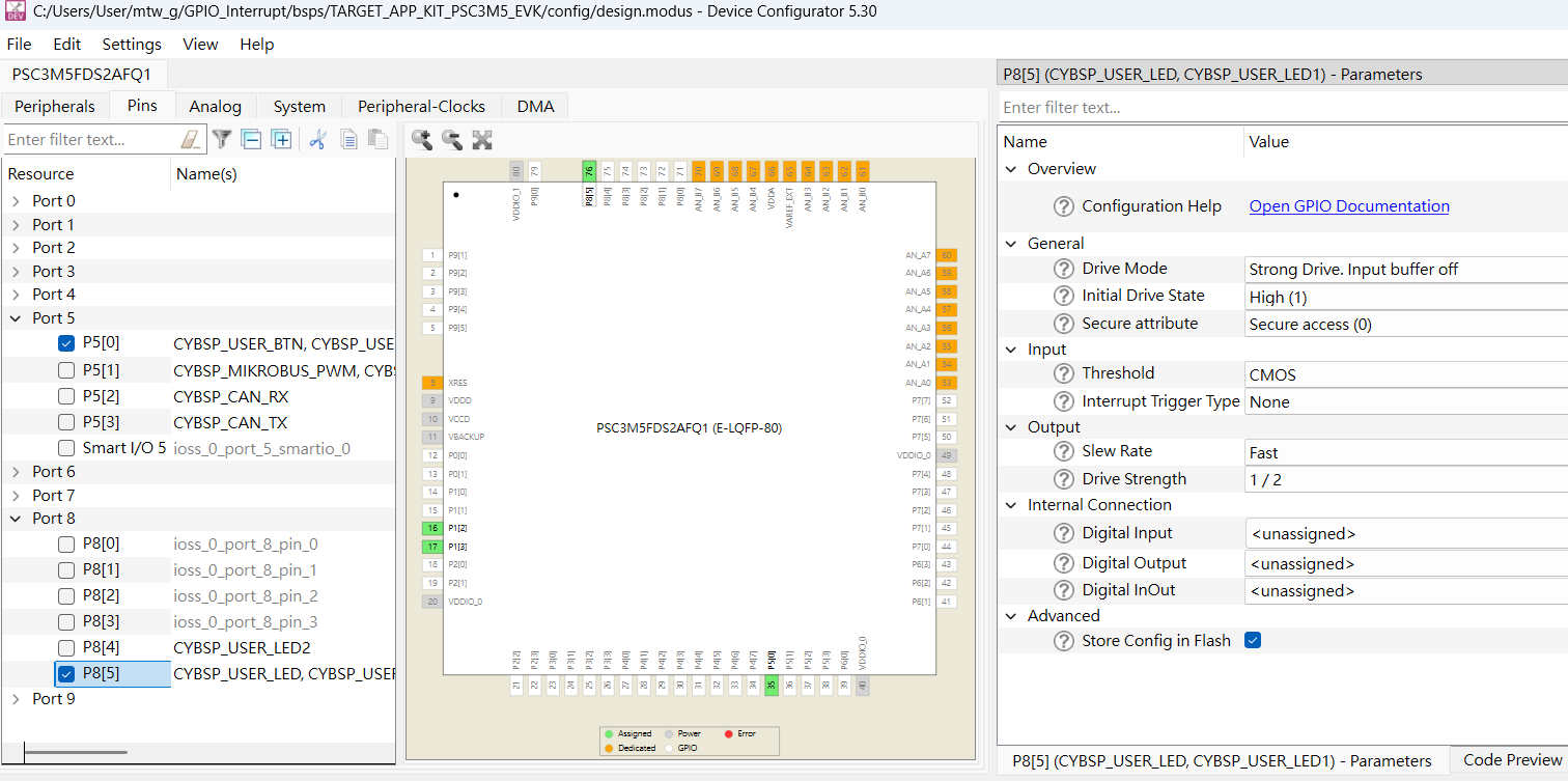
9. Because the SW4 switch of KIT_PSC3M5_EVK is connected to P5.0, and the Blue LED is connected to P8.5.
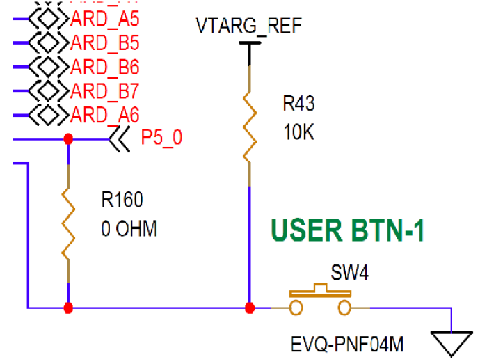
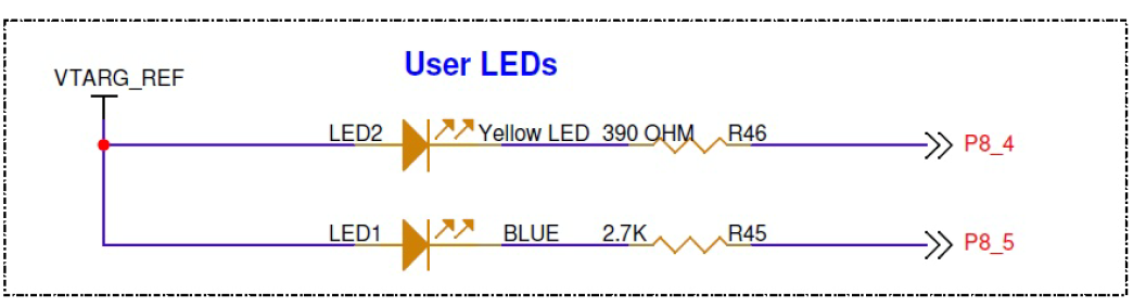
So the parameter configuration in the device configurator is as follows,
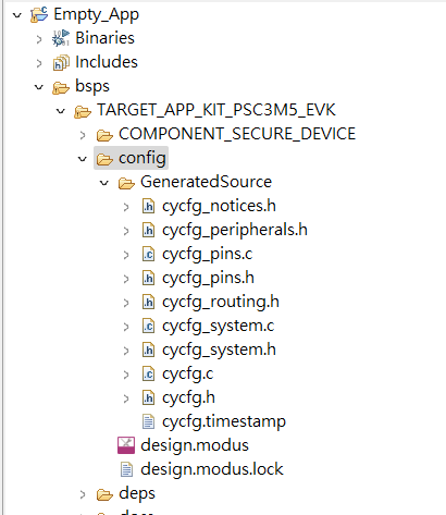
10. After the configuration is complete, ModusToolbox™ has not generated the code yet. You need to click 'Generate Launches for Empty_App' under Launches. Once completed, you can view it through bsps→config→GeneratedSource.
12. Next, the main program can be configured in the following order.
#define GPIO_INTERRUPT_PRIORITY 7
#define DELAY_SHORT_MS          (250)   /* Milliseconds */
#define DELAY_LONG_MS           (500)   /* Milliseconds */
#define LED_BLINK_COUNT         (4)

    /* Initialize user button */
    Cy_GPIO_Pin_SecFastInit(CYBSP_USER_BTN_PORT, CYBSP_USER_BTN_PIN, CY_GPIO_DM_PULLUP, 1UL, HSIOM_SEL_GPIO);

    /* Configure GPIO5.0 interrupt vector */
    Cy_SysInt_Init(&intrCfgBTN, BTN_interrupt_handler_PDL);
    NVIC_EnableIRQ(ioss_interrupts_sec_gpio_5_IRQn);

    /* Enable global interrupts */
    __enable_irq();

    for (;;)
    {
        /* Check interrupt status */
        if (true == gpio_intr_flag)
        {
            gpio_intr_flag = false;

            /* Update LED toggle delay */
            if (DELAY_LONG_MS == delay_led_blink)
            {
                delay_led_blink = DELAY_SHORT_MS;
            }
            else
            {
                delay_led_blink = DELAY_LONG_MS;
            }
        }
        /* Blink LED four times */
        for (count = 0; count < LED_BLINK_COUNT; count++)
        {
            Cy_GPIO_Write(CYBSP_USER_LED_PORT, CYBSP_USER_LED_PIN, CYBSP_LED_STATE_ON); /* LED ON */
            Cy_SysLib_Delay(delay_led_blink);
            Cy_GPIO_Write(CYBSP_USER_LED_PORT, CYBSP_USER_LED_PIN, CYBSP_LED_STATE_OFF); /* LED OFF */
            Cy_SysLib_Delay(delay_led_blink);

        }
        /* Enter deep sleep mode */
        Cy_SysPm_CpuEnterDeepSleep(CY_SYSPM_WAIT_FOR_INTERRUPT);

    }
Interrupt subroutine
static void BTN_interrupt_handler_PDL()
{
    /* Clear the pin interrupt logic. This needs to be cleared to detect the next interrupt */
    Cy_GPIO_ClearInterrupt(CYBSP_USER_BTN_PORT, CYBSP_USER_BTN_PIN);
    gpio_intr_flag = true;

}
Example explanation
Why use Cy_GPIO_Pin_SecFastInit?
- Faster than the standard Cy_GPIO_Init(), omitting a bunch of parameters, only suitable forSimple GPIOUsage.
- Quickly set up simple pins (such as buttons and LEDs) to make the code more concise.
/* Initialize the user button */
Cy_GPIO_Pin_SecFastInit(CYBSP_USER_BTN_PORT, CYBSP_USER_BTN_PIN, CY_GPIO_DM_PULLUP, 1UL, HSIOM_SEL_GPIO);
Set the interrupt for GPIO5.0
- Cy_SysInt_Init():
Set up aInterrupt vectorPass intrCfgBTN (a configuration structure) into it.
It will include which hardware interrupt source to connect to and which interrupt handler function (BTN_interrupt_handler_PDL) to call when triggered. - Cy_SysInt_Init():
Set up aInterrupt vectorPass intrCfgBTN (a configuration structure) into it.
It will include which hardware interrupt source to connect to and which interrupt handler function (BTN_interrupt_handler_PDL) to call when triggered. NVIC_EnableIRQ():
Enable the interrupt corresponding to GPIO5.0 in the NVIC (Nested Vector Interrupt Controller).。
The IRQ ioss_interrupts_sec_gpio_5_IRQn is connected to a certain pin (e.g., 5.0) of GPIO port 5.
/* Configure GPIO5.0 interrupt vector */
Cy_SysInt_Init(&intrCfgBTN, BTN_interrupt_handler_PDL);
NVIC_EnableIRQ(ioss_interrupts_sec_gpio_5_IRQn);
Enable global interrupt
- __enable_irq() is an instruction for ARM Cortex-M CPUs.
- It willEnable the CPU to receive any interrupt signals.。
Switch LED blinking speed
/* Update LED toggle delay */
if (DELAY_LONG_MS == delay_led_blink)
{
    delay_led_blink = DELAY_SHORT_MS;
}
else
{
    delay_led_blink = DELAY_LONG_MS;
}
- delay_led_blink is a variable used to store the current time interval (in milliseconds) for the LED to blink.
- If it's currently a long interval (slow flashing), change it to a short interval (fast flashing).
- If it's short, change it back to long.
Each time the button is pressed, the LED blinking speed willSwitch between fast/slow。
Make the LED blink four times
/* LED blinks four times */
for (count = 0; count < LED_BLINK_COUNT; count++)
{
    Cy_GPIO_Write(CYBSP_USER_LED_PORT, CYBSP_USER_LED_PIN, CYBSP_LED_STATE_ON); /* LED ON */
    Cy_SysLib_Delay(delay_led_blink);
    Cy_GPIO_Write(CYBSP_USER_LED_PORT, CYBSP_USER_LED_PIN, CYBSP_LED_STATE_OFF); /* LED OFF */
    Cy_SysLib_Delay(delay_led_blink);
}
- LED_BLINK_COUNT is usually set to 4, indicating that it needs to blink 4 times.
- Cy_GPIO_Write() controls the GPIO levels, toggling between high and low to turn the LED on or off.
- Cy_SysLib_Delay() is a blocking delay, measured in milliseconds (ms).
This is where the LED blinks four times, with the interval depending on the new delay set after the button was just toggled.
Enter deep sleep
/* Enter deep sleep mode */
Cy_SysPm_CpuEnterDeepSleep(CY_SYSPM_WAIT_FOR_INTERRUPT);
- This line makes the MCUEnter Deep Sleep mode, saving power consumption.
- CY_SYSPM_WAIT_FOR_INTERRUPT means that the CPU can be woken up as long as there is an interrupt (e.g., pressing a button).
After the LED flashes 4 times, the MCU will enter ultra power-saving mode and wait for the next button wake-up.
Summary of the entire process
- Initialize button interrupt → Allow interrupt entry.
- The MCU main program is idling and waiting.
- Click the button → An interrupt occurred → The software sets gpio_intr_flag to true.
- The main program detected the gpio_intr_flag and switched the LED blinking speed.
- The LED flashes four times.
- After flashing, the MCU enters deep sleep mode, waiting for the next wake-up.
Conclusion
Through this example, we demonstrate the ability of the PSOC Control C3 MCU to wake up the CPU using GPIO interrupts in low-power mode and execute the ISR in real-time. This design approach effectively combines system power management with high real-time responsiveness, making it particularly suitable for scenarios in HVAC and heat pump equipment that require long standby periods but need to quickly respond to external events. The PSOC Control C3 not only offers powerful computational performance and rich motor control features but also showcases exceptional design flexibility in low-power operation and interrupt management. Combined with the development resources of ModusToolbox™, developers can more quickly implement similar low-power interrupt applications, accelerating the product development process while meeting the stringent requirements of modern HVAC systems for performance, power efficiency, and real-time responsiveness.