Continuing from the previous blog post: MediaTek Genio 130/130A Quick Start Guide (Part 5), we have implemented a UART example using the SDK.
In this post, we will guide you through implementing another example: SPI LED control
- Development using the Genio 130A HDK
- Pin selection and Pinmux configuration
- Implementation of Application function and CLI command
- Test results
Example: SPI LED control
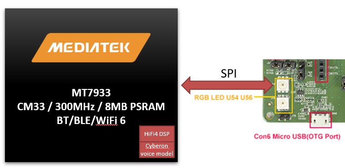
The SPI interface is widely used for communication and control of peripheral devices. In this blog post, we will use SPI to control an RGB LED, enabling LED lighting and color control functionalities.
** The RGB LED requires only two pins: SPI Clock and MOSI.
GPIO pin selection
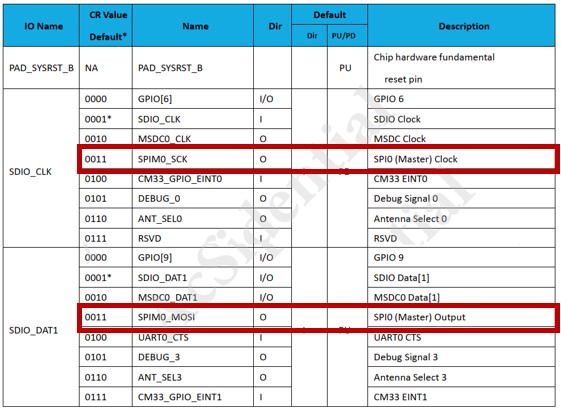
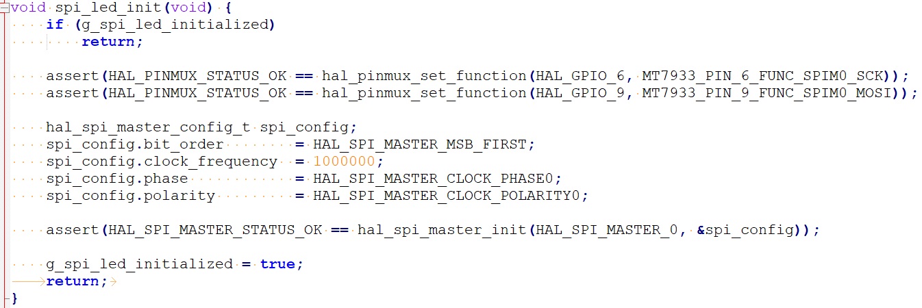
Referring to the HDK User Guide provided by AcSip, we selected GPIO_6 and GPIO_9 as the Clock and MOSI for SPI0.
The hal pinmux configuration is the same as in the previous blog post, achieved by calling the function hal_pinmux_set_function().
SPI Application & LED command
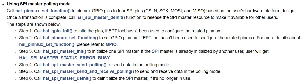
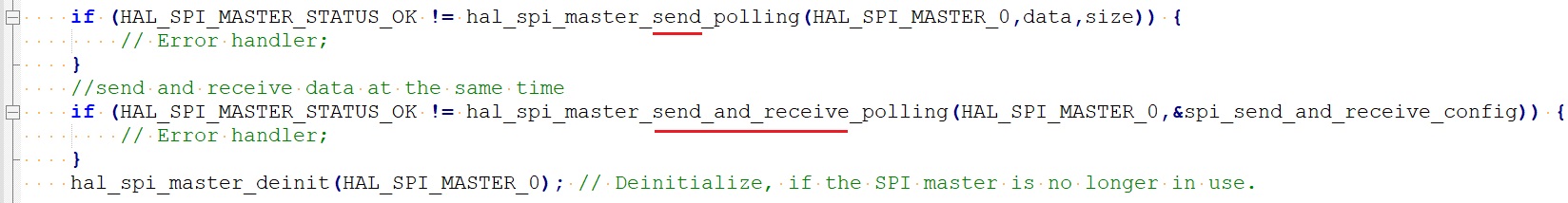
The SPI in the MediaTek Genio 130/130A SDK supports two modes: Polling mode and DMA mode. In this post, we will use Polling mode for implementation. The following process is used to implement SPI initialization and data transmission in Polling mode:
SPI Master Operation Flow
SPI Master Initialization
SPI Master Data Transmission
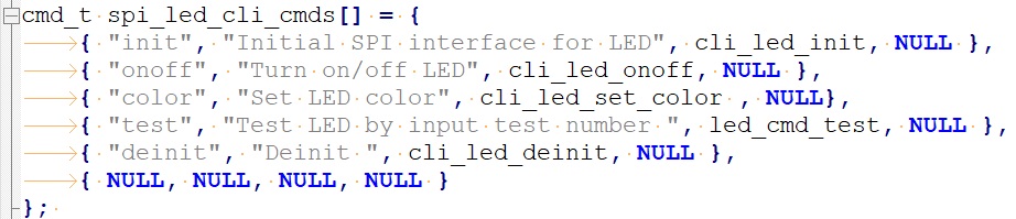
For LED control, we created a CLI command to link the LED control commands to the SPI API function.
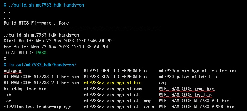
Build image & flash
Below are the program files that were modified/added for this example (for reference):
Modified files:
- GCC/feature.mk
- GCC/Makefile
- src/cli_cmd.c
- inc/spi_led.h
- src/spi_led.c
Testing
We rebooted the Genio 130A HDK, and the SPI LED CLI command and its description can be found in the console.
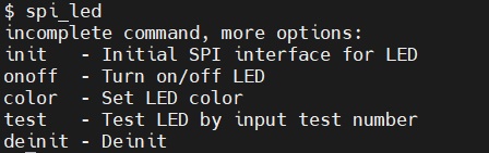
CLI command example:
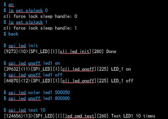
Test results:
Related information links:
- MediaTek Genio 130/130A: https://www.mediatek.com/iot/products/genio-130
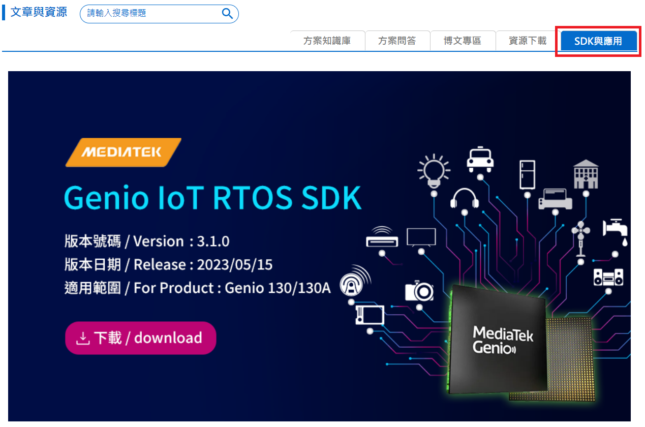
- MTK Genio130/130A Non-NDA SDK (refer to the image below): https://www.wpgdadatong.com/product-channel/Mediatek