
The full English name of FEM is front-end module, also known as RF front-end module.WiFi-FEM refers to a module used in WiFi communication that integrates a series of RF front-end circuits, such as power amplifiers (PA), RF switches, low-noise amplifiers (LNA), filters, and duplexers. Currently, the mainstream integration method for WiFi-FEM products is the form that combines power amplifiers, RF switches, and low-noise amplifiers.
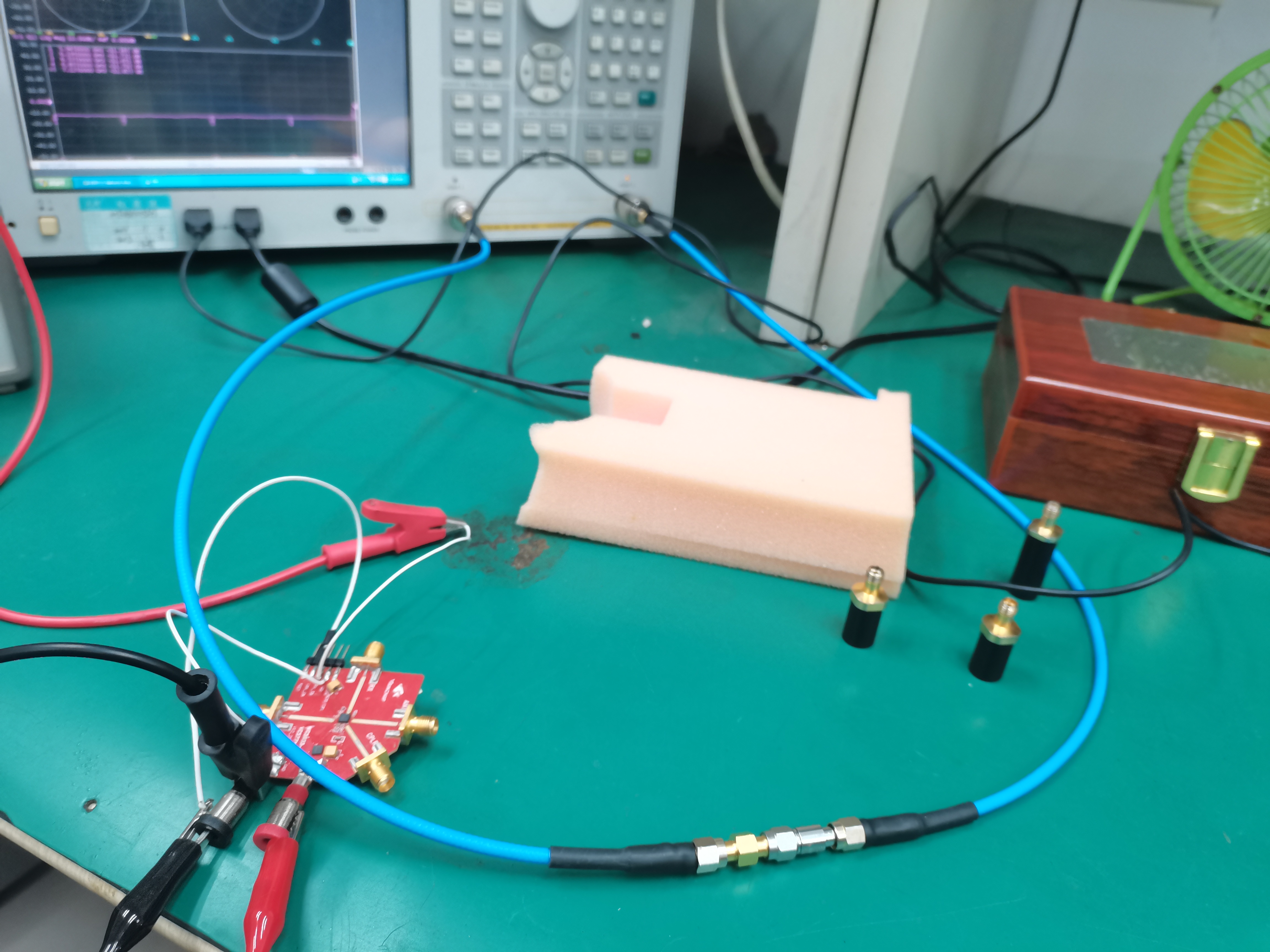
Since the FEM is an amplifier, if we want to understand the actual amplification factor of this chip, which is the gain, how should we test it? Below, we will use the VC5871-11 6G band FEM chip and the Agilent Technologies E5071C as examples to introduce the testing method steps.
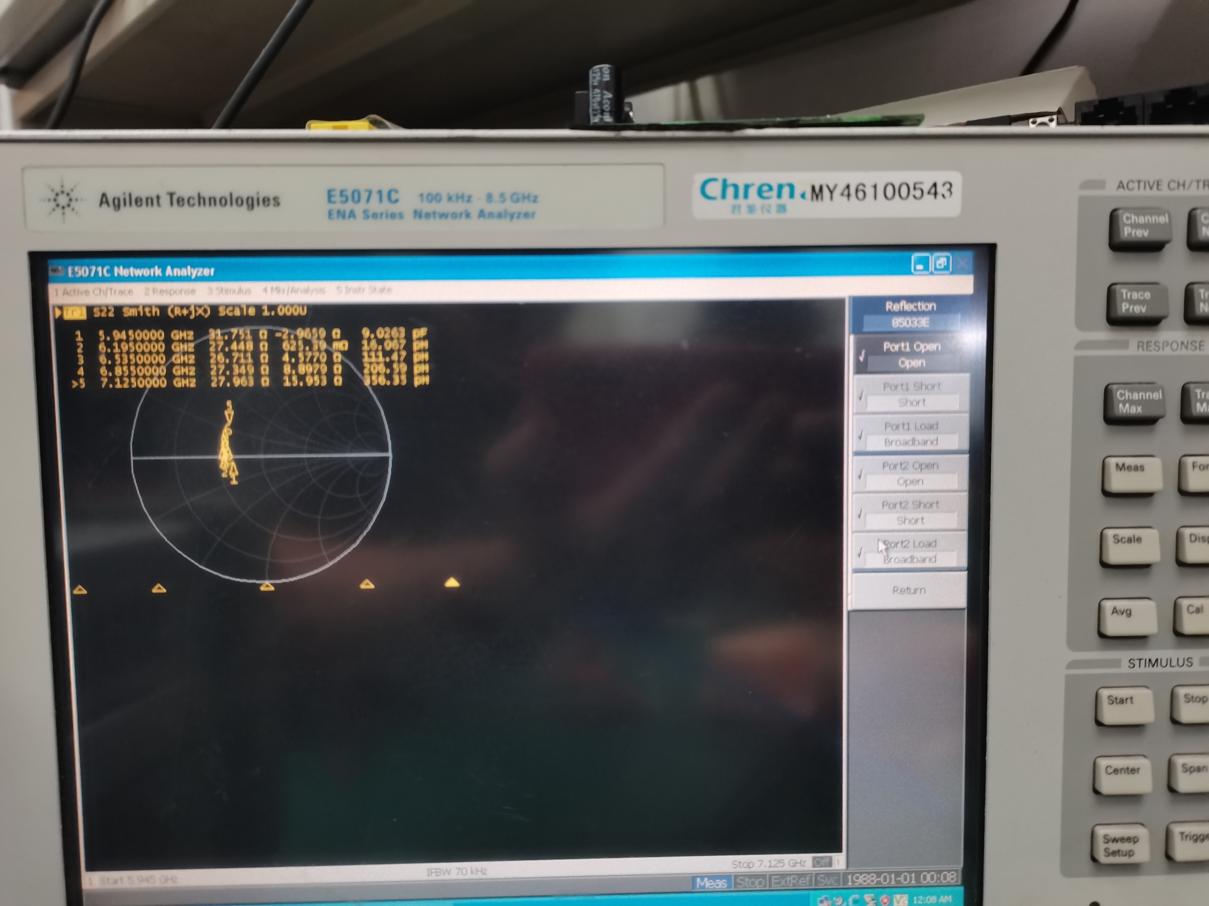
For general testing gain, in order to prevent excessive output power, an attenuator of more than 10dB is added, and ports 1 and 2 are calibrated.
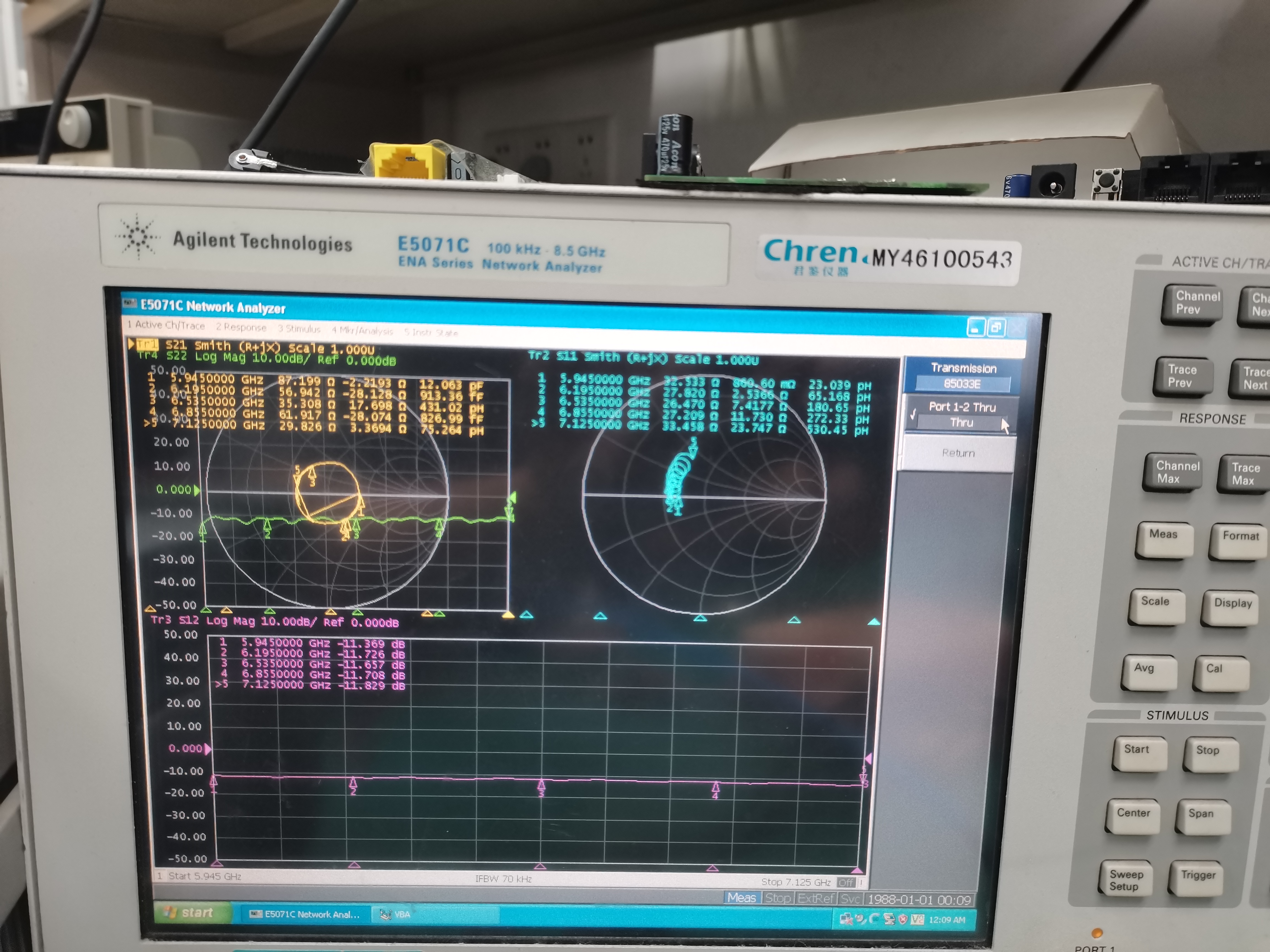
Simultaneously calibrate pass-through:
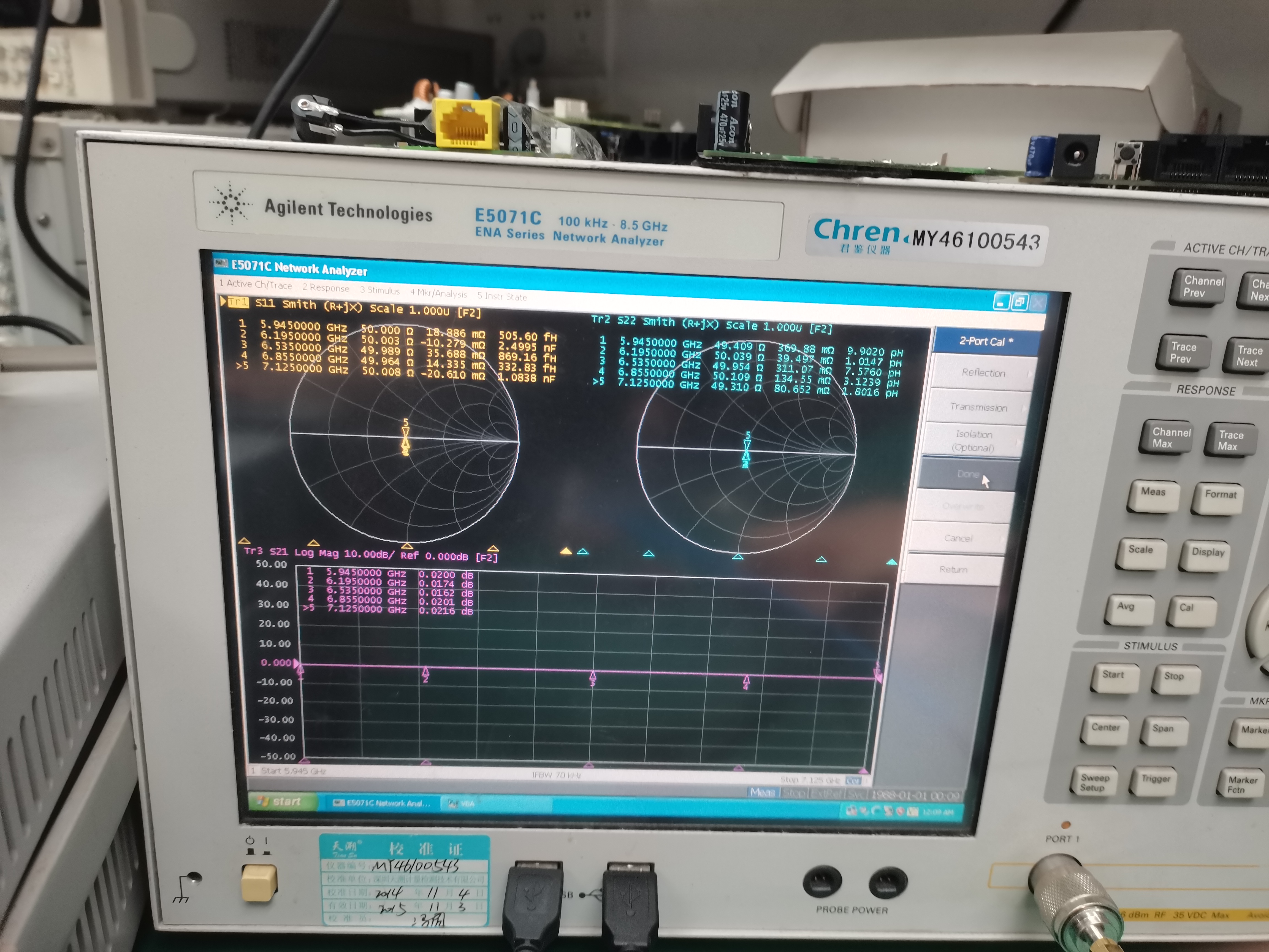
- Finally, click 'Done' to save the test project.
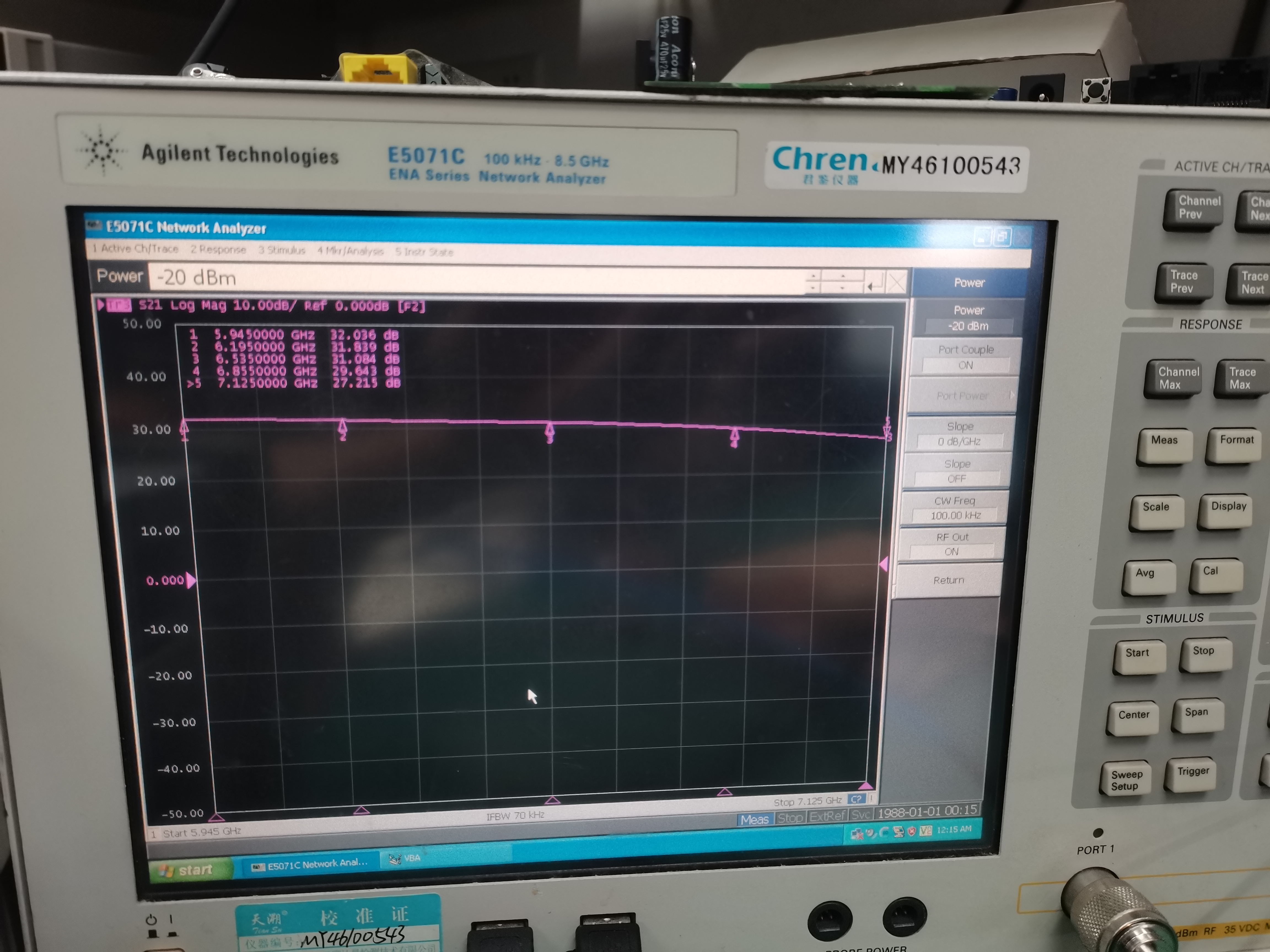
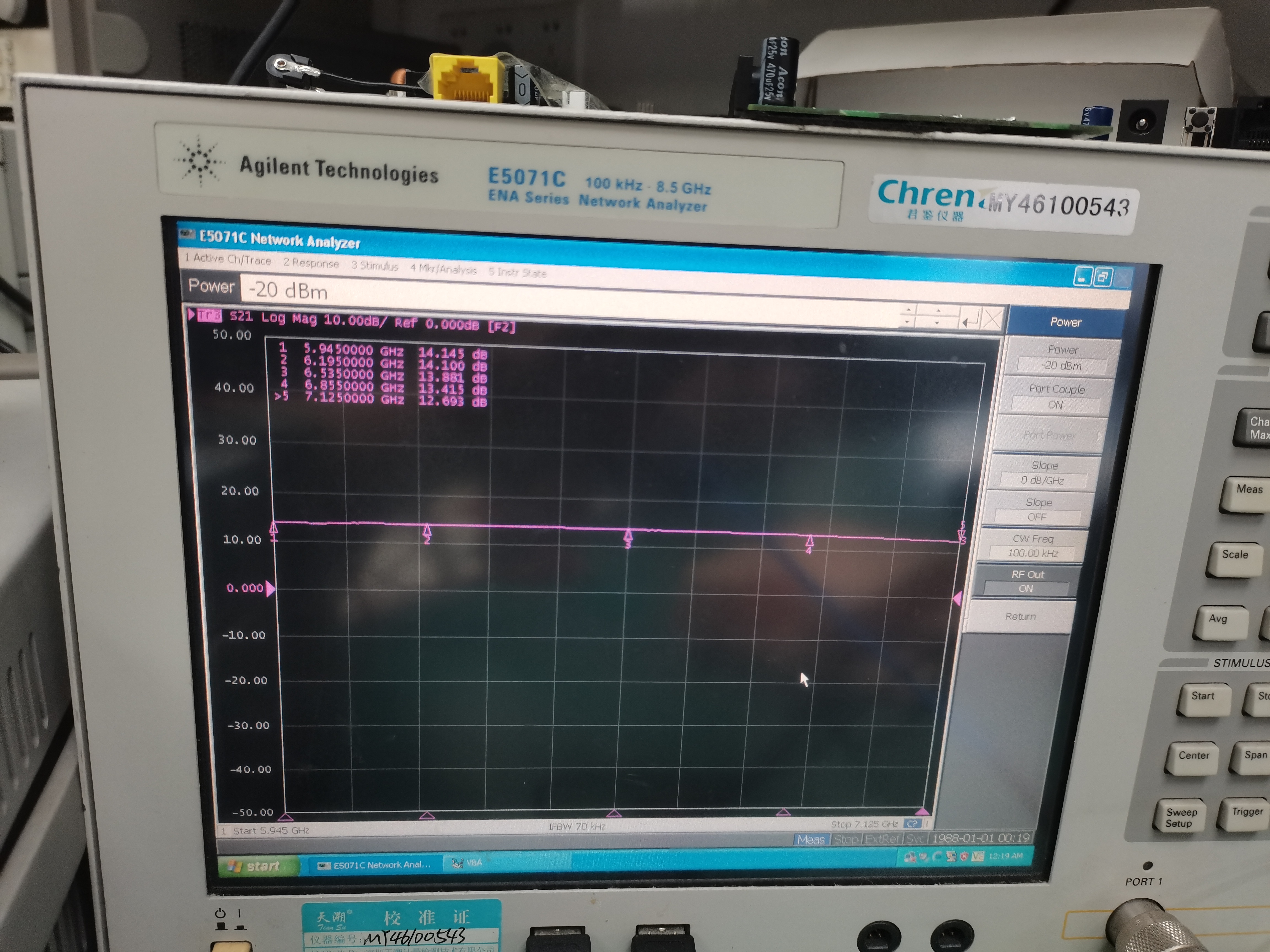
4. Click on power, set the input power not to exceed -20dBm, and open the RF out port.
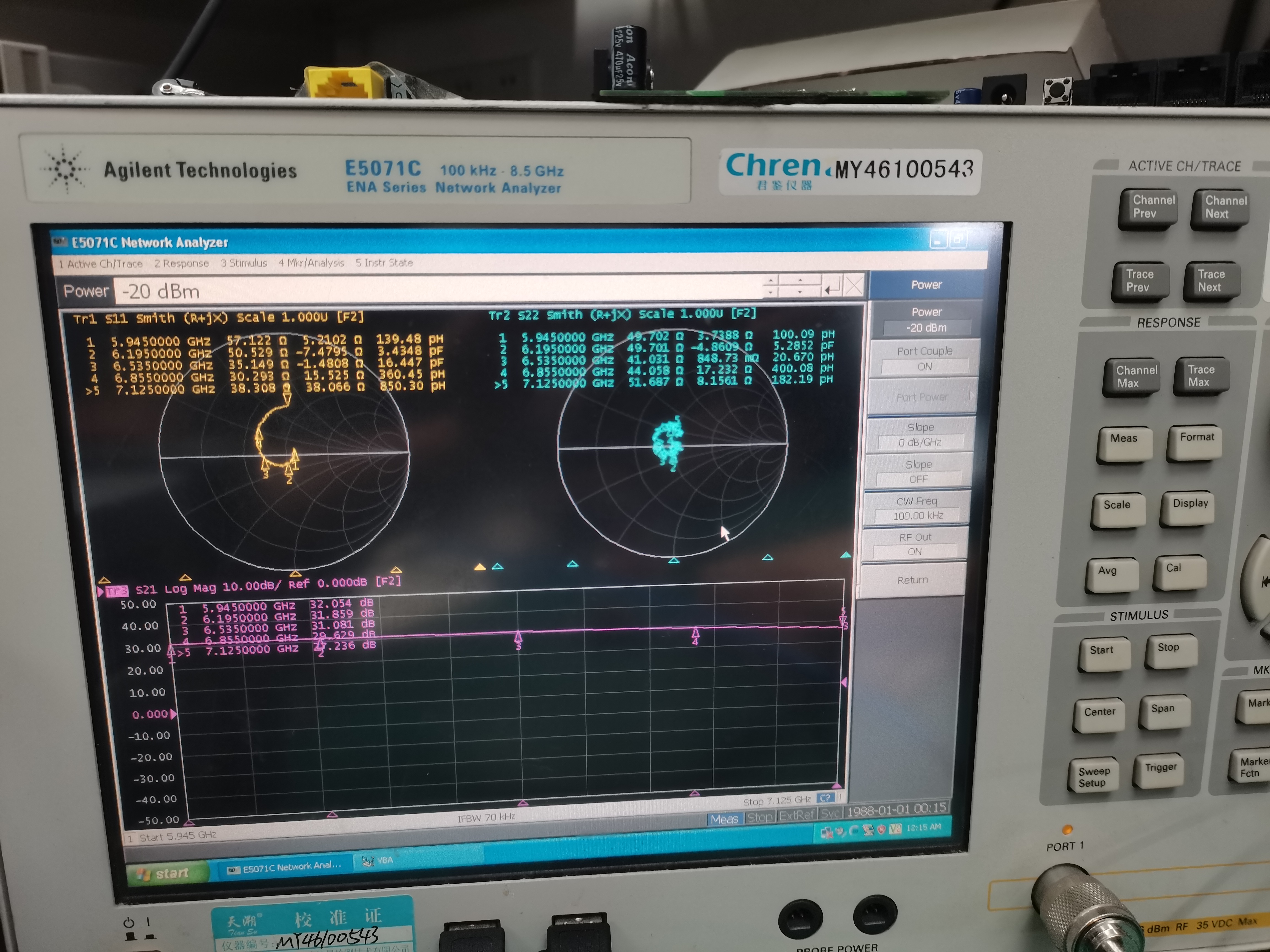
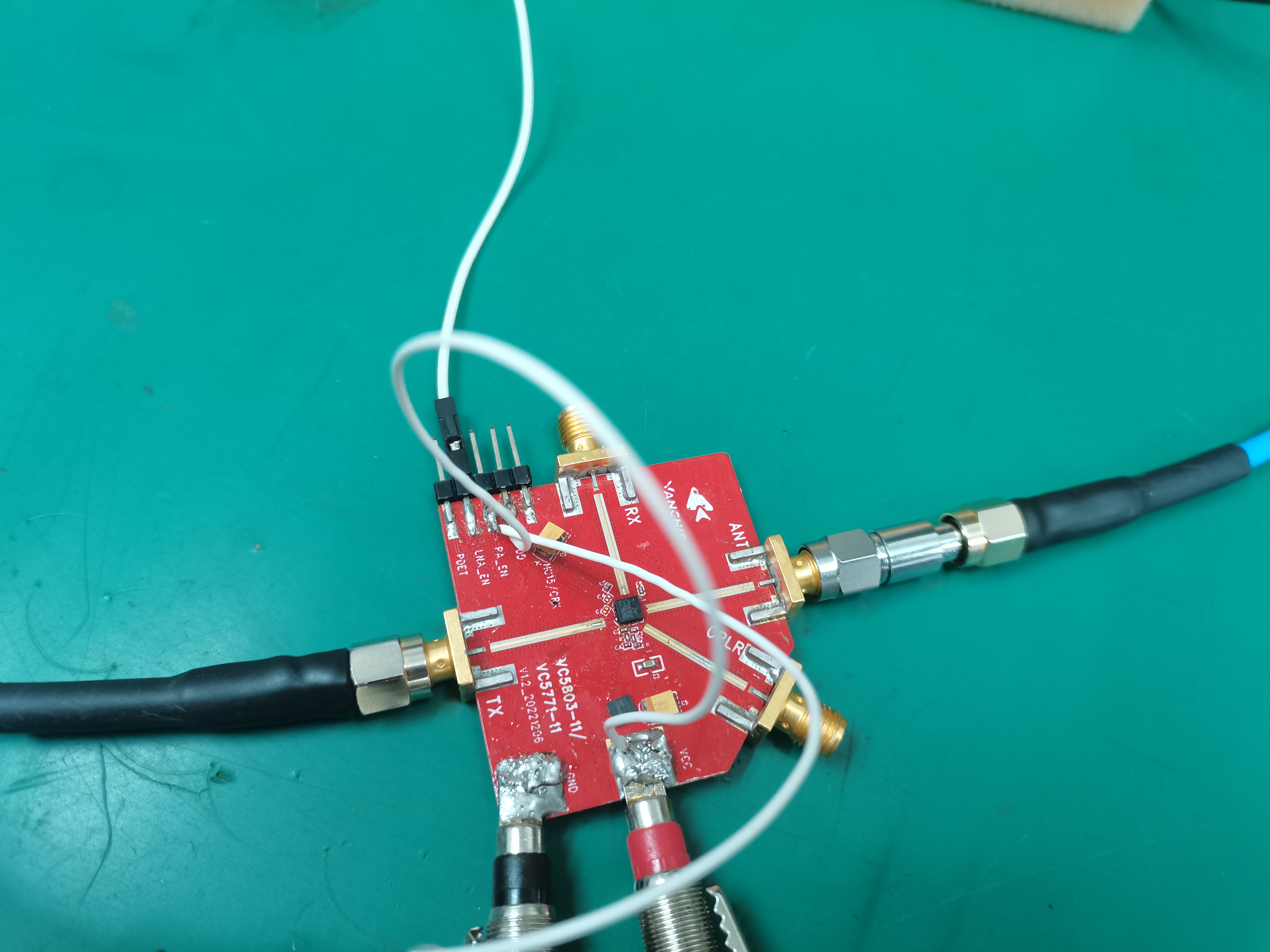
5. Port 1 is connected to TX, Port 2 is connected to ANT, the module is powered on, FEM operates, TX is enabled, and the TX gain is tested.
Test whether the gain of multiple bias points matches the standard specified in the datasheet.
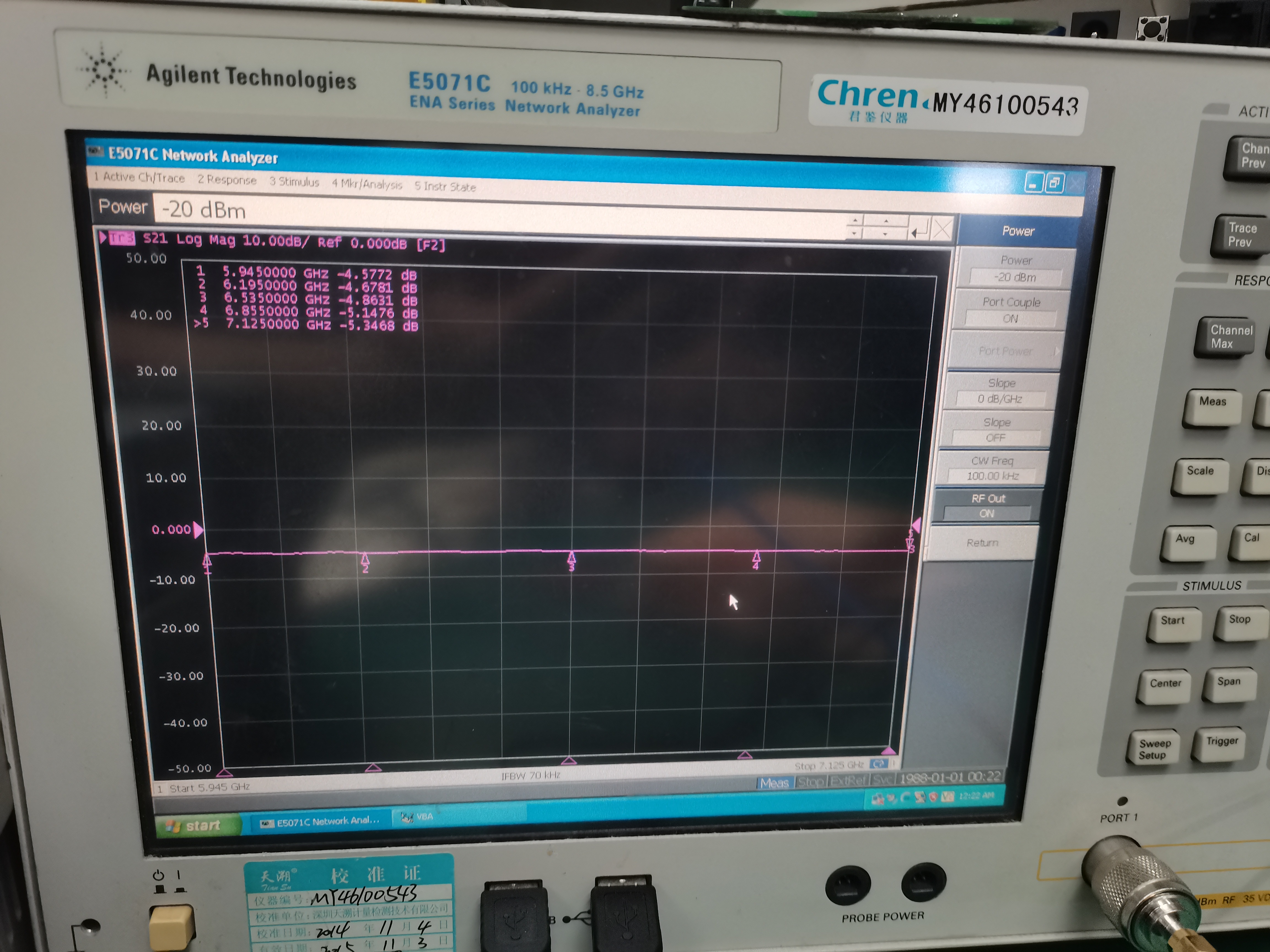
6. Test the gain of RX, connect port 1 to ANT, port 2 to RX, and enable RX.
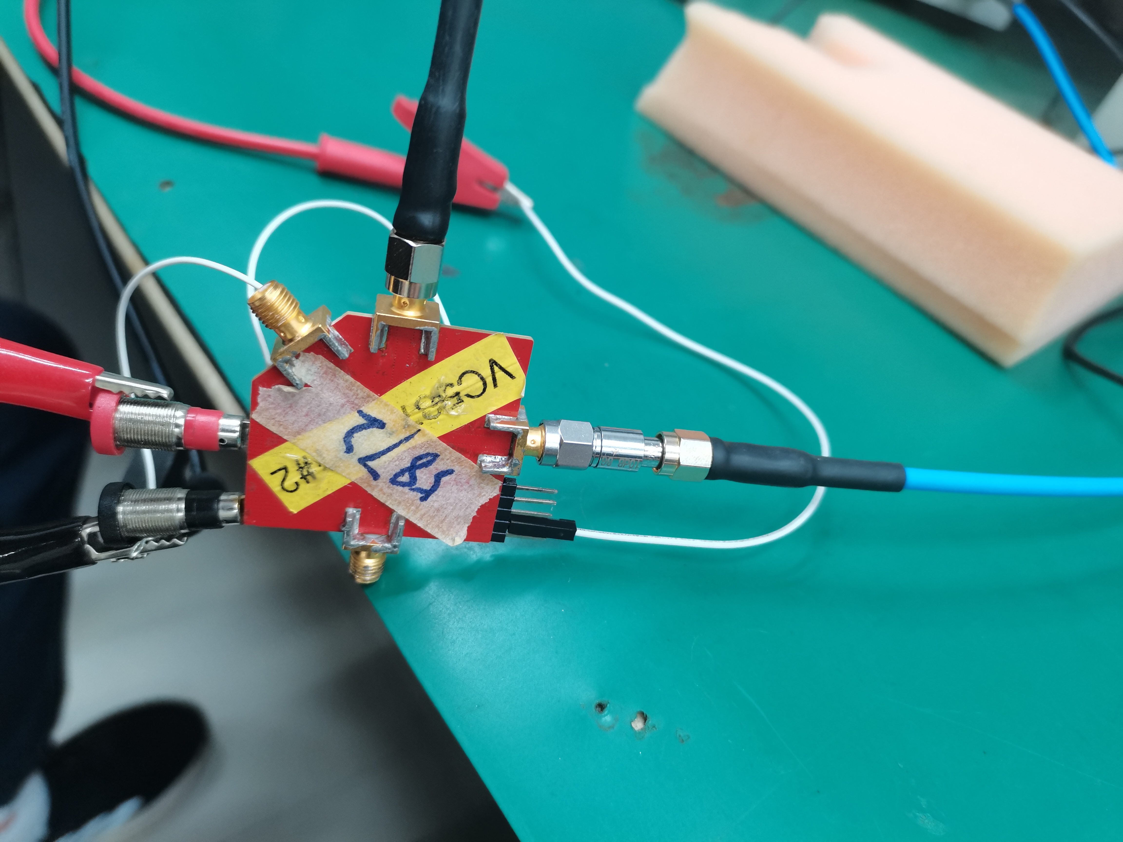
7. Test the gain of the LNA. Since the LNA mode is also a type of RX mode, connect port 1 to ANT and port 2 to RX, then enable the LNA.
Q1: Can this method test the gain of other frequency bands?
A1: Regardless of whether it's 2.4G/5G/6G FEM, the steps are the same. The only difference is during the calibration phase, where the test frequency and frequency band need to be adjusted.
Q2: After powering on, is the network analyzer unable to test data?
A2: It is necessary to check whether the module is powered on and whether the FEM enable connections are correct.
Q3: What should be done if the test results differ from the specifications?
A3: It could also be due to a gap between the boards, or the capacitors on them might be slightly different. Generally, a difference of 0.5dBm to 1dBm is considered normal.
Q4: Why is the RX test port different from the TX test port?
A4: Port 1 has always been used as the transmitter, and port 2 as the receiver. Therefore, testing RX is exactly the opposite of TX, and it needs to be swapped.
Q5: Is it possible to calibrate without adding an attenuator?
A5: It can be omitted, but to prevent improper operation and settings that may result in excessive output power and damage to the equipment, it is generally included.