

In modern electronic systems, efficient power management is crucial for ensuring system stability and extending battery life. Protection switches can simplify power control and protection for various loads, making them one of the key components. Compared to discrete MOSFET solutions, integrated protection switches offer advantages such as smaller size, stronger protection features, and simplified design.
Launched by RichtekRT1985/RT86/RT198197 is a high-performance ideal diode protection switch, specifically designed for USB-C / Thunderbolt power delivery, Docking Station, and Power ORing architectures in modern electronic systems. This application note will introduce the product features, application cases, and design considerations.
Key functional features of protective switches
RT1985/RT1986/RT1987Featuring low forward voltage drop, adjustable soft start, startup short-circuit protection, and comprehensive fault protection functions, it effectively simplifies power path management design and enhances overall system reliability. Compared to discrete MOSFET solutions,RT1985/RT1986/RT1987Provides a smaller package size, better integration, and enhanced protection features.
| Product | Mobile Vin | Maximum continuous current | OVP threshold | Package |
| RT1985 | 3.4V to 23V | 8A | Fixed | VDFN-12TL 3x3 |
| RT1986 | 3.4V to 23V | 5.5 amps | Fixed | VDFN-12TL 3x3 |
| RT1987 | 3.4V to 32V | 8A | Programmable | VDFN-12T1L 3x3 |

Figure 1. Functional characteristics of the protective switch
1.1 Power Control (Switch Control)
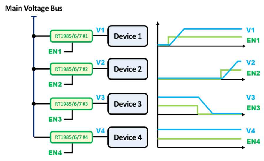
The protection switch does not require mechanical relays and can easily achieve load power on/off control, facilitating power sequencing and dynamic power management.RT1985/RT1986/RT1987Through the active-high EN pin, precisely control the timing of power path activation. When EN is at a high level and the input voltage exceeds the UVLO threshold, the power channel will activate after a specified delay time, featuring a controllable voltage ramp-up rate to ensure a stable and reliable power-up process.
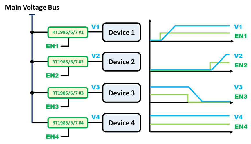
Figure 2. Activation control of the protection switch
1.2 Adjustable Soft Start and Surge Current Control
Many protection switches achieve built-in soft-start functionality by controlling the gate drive voltage, allowing the output voltage and current to rise smoothly.RT1985/RT1986/RT1987Supports external soft-start capacitors. Designers can use soft-start capacitors to design the output voltage slope and limit inrush current, preventing interference with the main power line. This is particularly suitable for systems with large capacitive loads. For detailed design recommendations, please refer to the product datasheet.
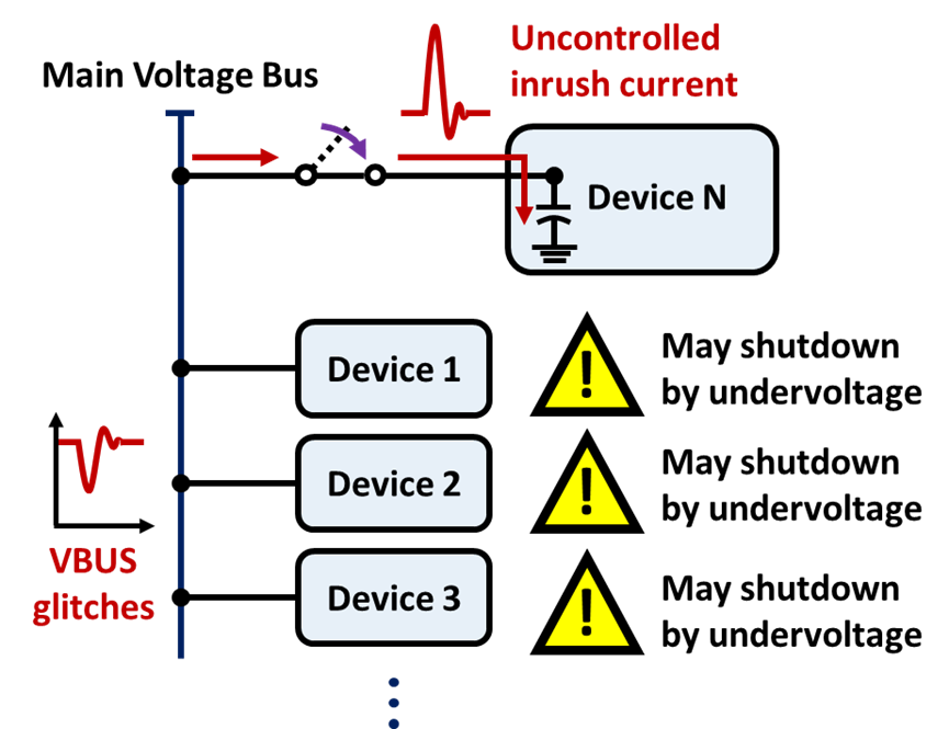
Figure 3. Startup without inrush current control
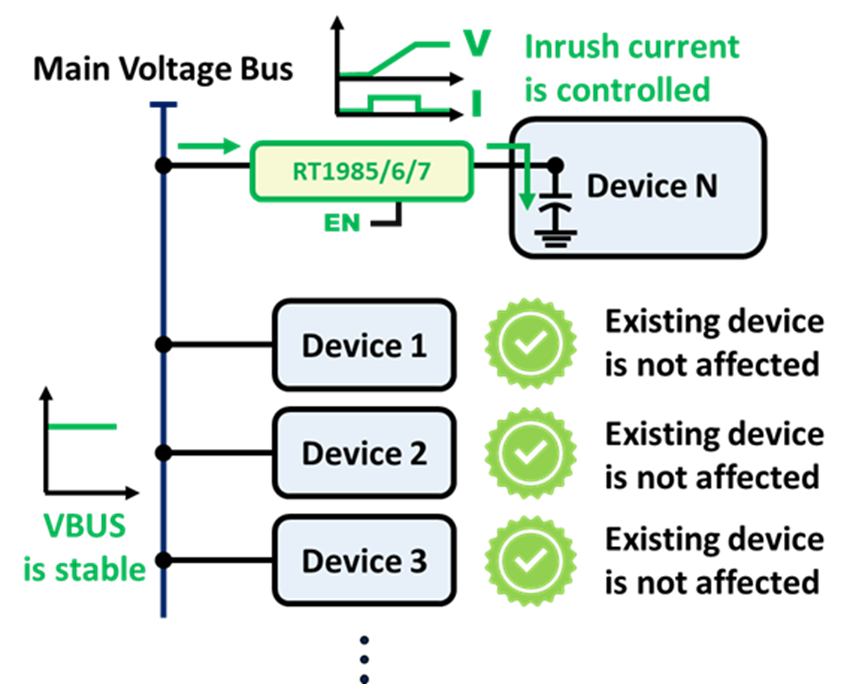
Figure 4. Startup with surge current control
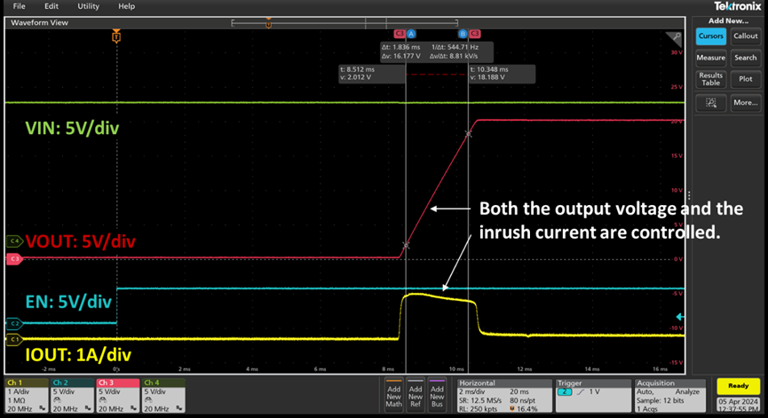
Figure 5.RT1985Soft start test results
1.3 Activate Short Circuit Protection (SCP)
During the startup process,RT1985/RT1986/RT1987The device will continuously monitor the output current. If an abnormal surge current or a hard short is detected, the device will proactively shut down the output and automatically restart (Auto Retry) after a specified delay time, ensuring safe protection even under fault conditions.

Figure 6. Application of MOSFET as a protective switch

Figure 7. UsageRT1985/RT1986/RT1987As an application of protective switches
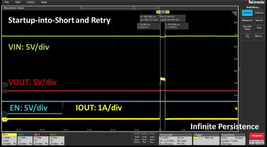
Figure 8.RT1985Test results for short circuit and restart during startup
1.4 Reverse Current Blocking
In multi-power redundancy or ORing systems, preventing current from flowing back to the input side is a crucial condition.RT1985/RT1986/RT1987Equipped with Ideal Diode True Reverse Current Blocking (TRCB) functionality, it can stably control the forward voltage drop and effectively prevent current from flowing back from VOUT to VIN, making it a key technology for implementing multi-source power supply applications.
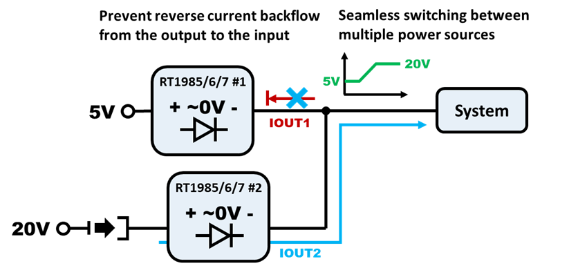
Figure 9. Reverse current blocking from the output to the input.
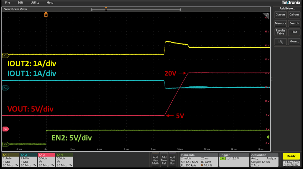
Figure 10.RT1985Reverse Current Blocking Protection Test Results
1.5 Overvoltage Protection (OVP)
RT1985/RT1986/RT1987Integrated input overvoltage protection function automatically disconnects the power path when the input voltage exceeds the threshold, preventing damage to downstream circuits. This feature is particularly suitable for USB-C and multi-source power supply architectures, effectively addressing voltage surges from unstable input sources.
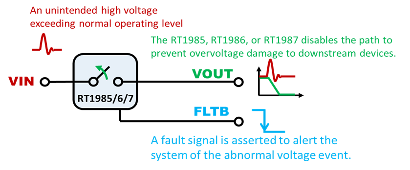
Figure 11. Overvoltage protection mechanism when the input voltage is too high
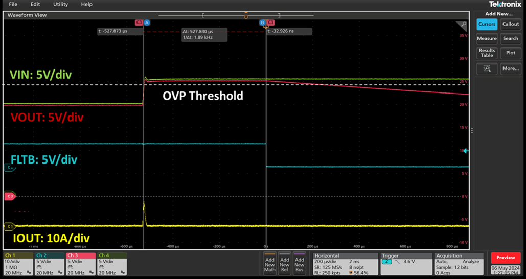
Figure 12.RT1985Overvoltage protection test results
1.6 Over-temperature Shutdown Protection
High-level protection switches typically have a built-in temperature monitoring mechanism. When the chip temperature exceeds the safety threshold (approximately 140°C),RT1985/RT1986/RT1987It will automatically shut down the output and activate an error prompt to prevent permanent damage, further enhancing system reliability.
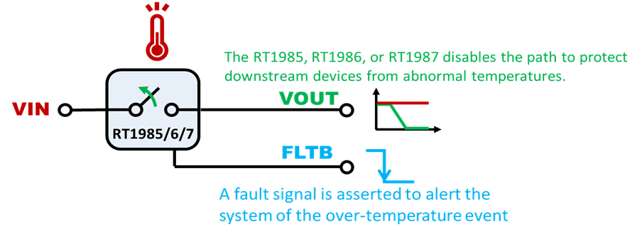
Figure 13. Over-temperature protection mechanism under abnormal high-temperature conditions
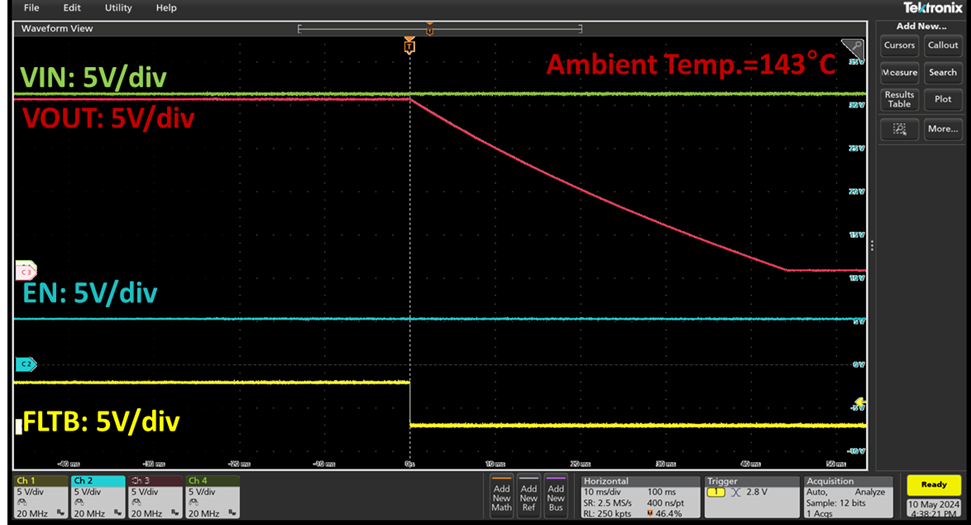
Figure 14.RT1985Over-temperature protection test results
1.7 Low on-resistance (20mΩ)
RT1985/RT1986/RT1987Designed with advanced technology, the internal MOSFET's on-resistance (R) is reduced to 20mΩ, minimizing power loss (P = I²R) during high current transmission. This not only reduces component heating but also enhances overall heat dissipation efficiency.
1.8 Extremely Low Static Current
RT1985/RT1986/RT1987Featuring an ultra-low quiescent current design, it means that the IC itself consumes very little power under no-load or light-load conditions, further optimizing the overall power consumption performance and extending battery life. This makes it suitable for use in portable devices such as laptops and tablets.
2 Application Examples
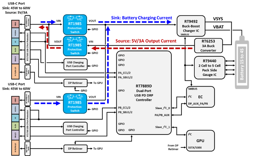
2.1 USB-C / Thunderbolt Sink Power Application
Protection switches play a critical role in USB-C and Thunderbolt applications, not only providing power control functionality but also safeguarding the system against surge and backflow risks during dynamic power negotiation processes.RT1985Capable of managing both Sink and Source power paths simultaneously, it is applied in dual-port USB PD devices.
Note: The system diagram above is for reference only. Actual application should be adjusted according to product specifications. For assistance, please contact the Richtek sales representative.
2.2 Expansion Docking Station
In the design of laptop and tablet docking stations, protection switches can be used to selectively enable various I/O ports or peripheral devices, improving system power efficiency, reducing standby power loss, and achieving fault isolation.
2.3 Multi-power ORing application
A protection switch with true reverse current blocking capability enables reliable multi-power ORing applications. Whether it's an AC adapter, battery, or backup power supply, seamless switching can be achieved to ensure uninterrupted power and enhance system stability.
3 Conclusion
Properly integrating protection switches can enhance system reliability, simplify power design, and optimize overall performance. In today's increasingly complex power architectures, protection switches have become an indispensable part of smart power management.RT1985/RT1986/RT1987Combining ideal diode reverse blocking, adjustable soft start, comprehensive protection features, and compact package design, it is the ideal choice for high-demand applications such as USB-C, docking stations, and power ORing. It helps designers simplify the development process, enhance product reliability, and improve user experience.
Source: Richtek Technology Corporation
►场景应用图
►展示板照片
►方案方块图
►核心技术优势
• Enhance system reliability • Simplify power design • Optimize overall performance
►方案规格
Voltage withstand: 23V, 32V; Current: 8A; ultra-low loss ideal diode.